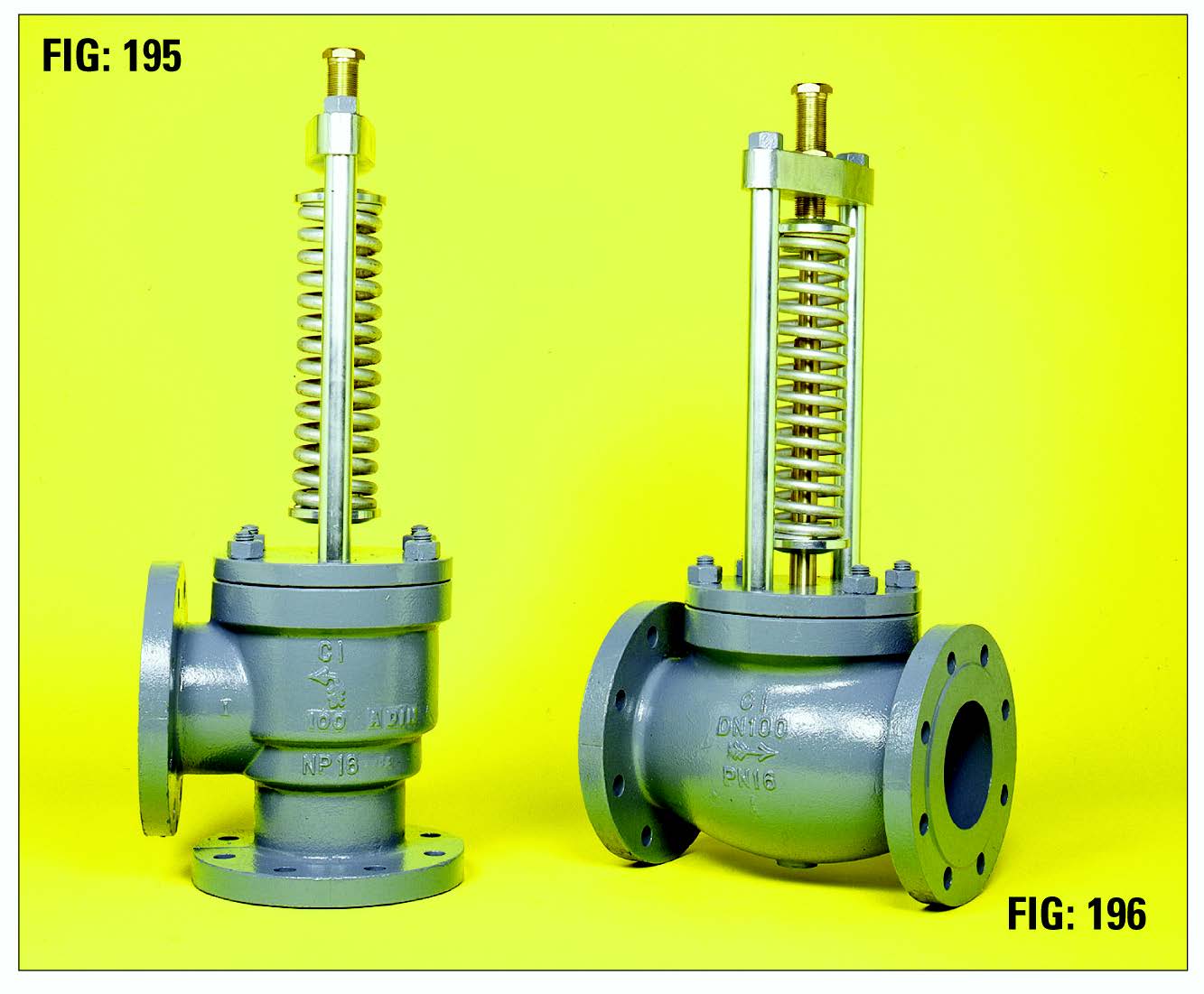
Cast Iron Relief Check for Liquids (external spring)

PRESSURE / TEMPERATURE RATING: (detailed on Valve ID Plate)
Min/Max spring set Pressures
Min Set Pressure 5psi (0.35 Bar)
Max Set Pressure 116psi (8.0 Bar)
MAX TEMPERATURE 40°C
FOR WATER INDUSTRY USE ONLY WITHIN THE EUROPEAN COMMUNITY
FLANGED:
- BS EN 1092-2 – PN6, PN10, PN16
- BS 10 TABLES – D, E, F
- ANSI B 16.1 – CLASS 125
CONSTRUCTION:
- This traditional design is suitable for systems with open discharge to atmosphere.
- The external spring is not in contact with the discharge liquid.
- The valve is intended to relieve excess liquid, and must not be used as a safety valve to prevent system failure as referenced in the Pressure Systems Safety Regulations SI 2000 No 128
- Flanges will be drilled unless otherwise specified on order
MATERIALS:
- Body/Cover – Cast Iron to BS EN 1561 EN GJL 250
- Disc – Stainless Steel Casting ASME SA 487 CA6NM class A
- Seat Ring – Stainless Steel Casting to BS EN 10283 1.4408
- Spring – Spring Alloy Steel Design in accordance with BS 1726 Chrome Vanadium Alloy Coated
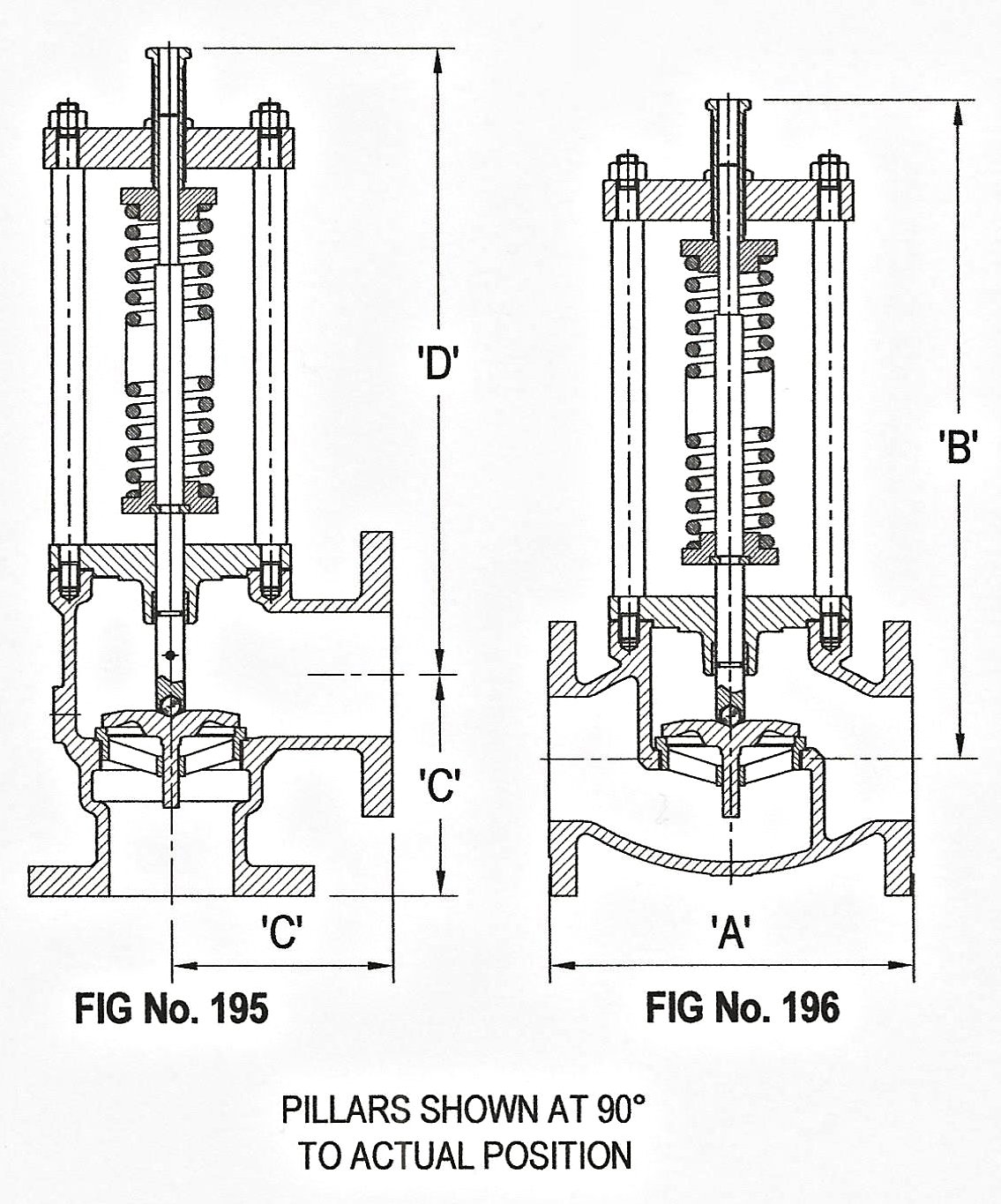
| Nominal Size (Fig.195) | 50 | 65 | 80 | 100 |
| A | 125 | 145 | 155 | 178 |
| B | 316 | 372 | 410 | 527 |
| Nominal Size (Fig.196) | 50 | 65 | 80 | 100 |
| A | 203 | 216 | 241 | 292 |
| B | 324 | 368 | 421 | 544 |

| STANDARD SPRING RANGE |
| Nominal Sizes 50mm to 100mm |
| Spring No. | PSI | Bar |
| 1 | 5-13 | 0.35-0.9 |
| 2 | 10-25 | 0.7-1.7 |
| 3 | 20-50 | 1.4-3.5 |
| 4 | 40-100 | 2.7-6.9 |
| 5 | 90-230 | 6.2-8.0 |
OPTIONAL EXTRAS:
- Easing Lever and cover Locking Unit
TYPE OF APPLICATION:
- Thermal & pressure relief
LINE MEDIA:
- Effluent
- Sewage Sludge
